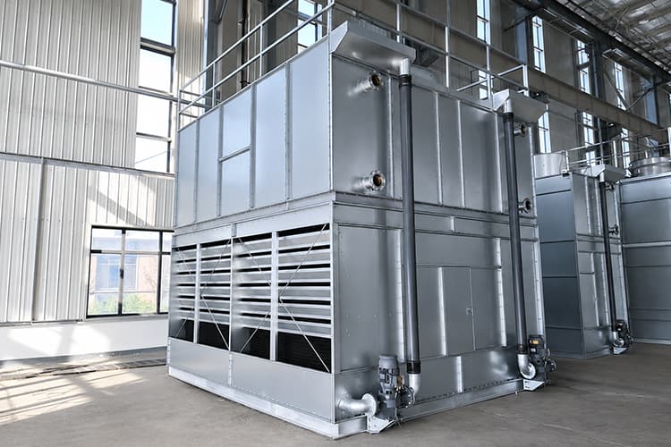
Fan-Side Access
Forced draft designs can provide convenient access to fan and motor components depending on the tower layout.
Thermocore forced draft closed circuit cooling towers are designed for HVAC, industrial process cooling,
equipment cooling, refrigeration support and manufacturing applications where clean process fluid, flexible airflow arrangement
and reliable evaporative heat rejection are important.
In a forced draft design, fans push air into the cooling tower from the inlet side. The process fluid remains isolated inside
the heat exchange coil, while spray water and forced airflow remove heat from the outside of the coil. This structure can be useful
for special installation layouts, lower fan position requirements and projects requiring convenient fan-side access.
A forced draft closed circuit cooling tower is a closed-loop evaporative cooling system where fans push air into the tower
instead of pulling air from the outlet side. The process fluid flows inside a heat exchange coil and does not directly contact
air or spray water. Heat is transferred through the coil wall to the spray water and forced airflow outside the coil.
This product is suitable for projects that require closed-loop fluid protection and a specific forced-air arrangement.
It can be selected for special site layouts, fan-side service access, low-position fan arrangements or customized industrial
cooling systems where standard induced draft configurations may not be the best fit.
The system removes heat through indirect evaporative cooling. Hot process fluid stays inside the coil.
Spray water flows over the coil surface, and forced draft fans push air into the heat exchange section.
A portion of spray water evaporates and carries heat away from the coil surface.

Forced draft design is selected when a project needs closed-loop fluid protection and a fan arrangement that pushes air into the tower.
This can be useful for special installation layouts, fan-side accessibility and customized airflow paths.
Forced draft designs can provide convenient access to fan and motor components depending on the tower layout.
Fans push air into the tower, allowing the airflow path to be adapted for some project-specific layouts.
The process fluid stays inside the coil and is not directly exposed to outside air or spray water.
Useful when equipment height, fan location, service space or air inlet direction requires a custom approach.
Supports process cooling systems that need stable heat rejection and fluid protection.
Coil material, casing, fan system, basin, pump, motor voltage and low-noise design can be customized.
Forced draft closed circuit cooling towers are used where the process fluid should remain protected and the project requires
a special fan or airflow arrangement. They are suitable for HVAC, industrial process cooling and equipment cooling applications.
Forced draft and induced draft closed circuit cooling towers both protect the process fluid inside a coil.
The main difference is whether the fan pushes air into the tower or pulls air through the tower.
| Item | Forced Draft Closed Circuit Cooling Tower | Induced Draft Closed Circuit Cooling Tower |
|---|---|---|
| Fan Function | Fan pushes air into the tower from the inlet side | Fan pulls air through the tower and discharges it from the outlet side |
| Airflow Characteristic | Positive pressure airflow through the heat exchange section | Negative pressure airflow through the heat exchange section |
| Fan Location | Often located near the air inlet or lower side section | Often located near the discharge section or top outlet |
| Maintenance Access | Fan-side access can be convenient depending on layout | Access depends on top discharge or outlet fan structure |
| Recirculation Consideration | Site layout should be reviewed to avoid warm moist air recirculation | Upward discharge can reduce recirculation risk when properly arranged |
| Best For | Special layouts, lower fan position, fan-side access or custom airflow paths | Standard outdoor installations with effective air discharge layout |
| Selection Logic | Choose when fan position and airflow arrangement are key project constraints | Choose when standard induced airflow and top discharge are preferred |
The key difference is fluid protection. Open towers expose circulating water directly to air, while forced draft closed circuit towers
keep the process fluid inside a coil and use spray water and forced airflow outside the coil for heat rejection.


| Item | Forced Draft Closed Circuit Cooling Tower | Open Cooling Tower |
|---|---|---|
| Fluid Protection | Process fluid stays inside the heat exchange coil | Circulating water directly contacts air |
| Contamination Risk | Lower in the main process fluid loop | Higher because water is exposed to air |
| Heat Transfer | Indirect evaporative cooling through coil surface | Direct evaporative cooling |
| Initial Cost | Usually higher | Usually lower |
| Maintenance Focus | Coil surface, spray water, fan, motor, basin and pump | Fill, basin, water distribution, water treatment and fan |
| Best For | Closed-loop process cooling with special fan or airflow arrangement | General condenser water and water cooling applications |
Selecting a forced draft closed circuit cooling tower requires accurate operating data and site layout information.
A professional selection should consider heat load, process fluid type, flow rate, temperatures, wet bulb, coil material,
spray water quality, airflow path, fan location and installation space.
| Parameter | Why It Matters |
|---|---|
| Cooling Capacity | Determines tower size and required heat rejection capability. |
| Process Fluid Type | Water, glycol or special fluid affects coil design and pressure drop. |
| Fluid Flow Rate | Affects coil sizing, heat transfer and pump selection. |
| Inlet Fluid Temperature | Defines the hot-side operating condition. |
| Outlet Fluid Temperature | Defines the target cooling result. |
| Wet Bulb Temperature | Key ambient limit for evaporative cooling performance. |
| Coil Material | Affects corrosion resistance, service life and fluid compatibility. |
| Spray Water Quality | Affects scaling, corrosion, nozzle performance and maintenance. |
| Fan / Airflow Layout | Determines whether forced draft arrangement is suitable for the project. |
| Installation Space | Influences tower structure, service access and air inlet clearance. |
| Noise Requirement | Affects fan selection, fan speed and low-noise configuration. |
Performance depends on the coil, fluid connections, spray system, forced draft fan, basin, pump, air inlet, drift control, casing and frame.
Each component should be selected to support stable heat rejection and long-term reliability.
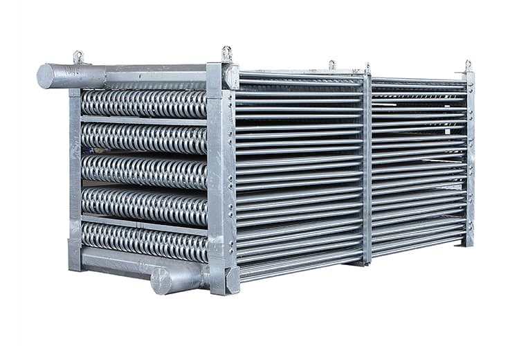
The core component where process fluid flows and transfers heat through the coil wall.
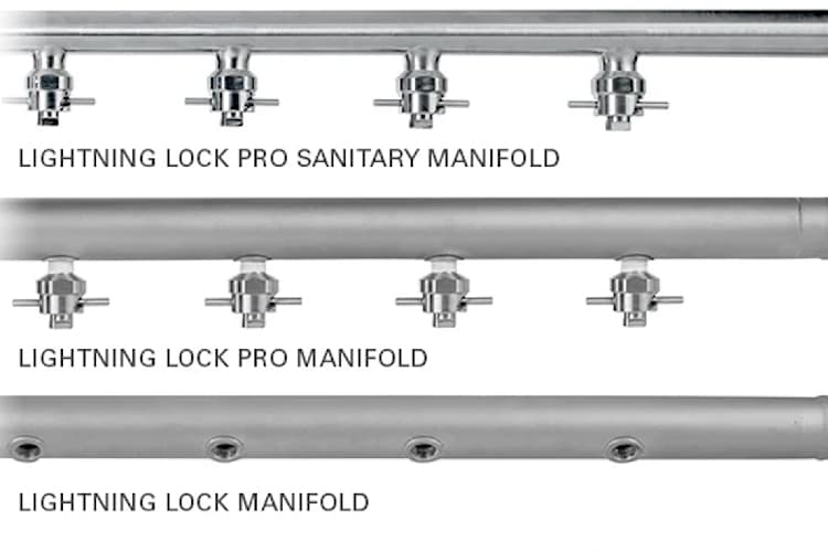
Distributes process fluid through the coil circuits and connect the tower to the closed loop system.

Distributes water over the coil surface for evaporative heat transfer.
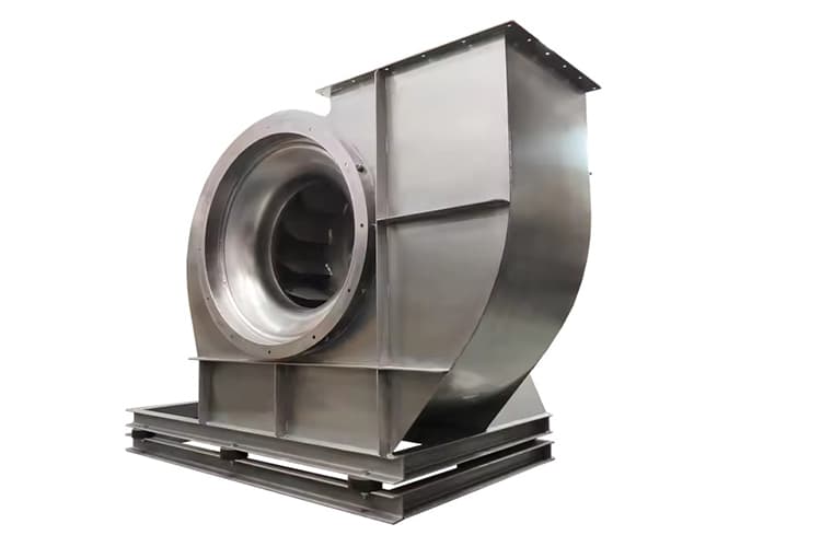
Pushes air into the tower from the inlet side and supports heat rejection.

Circulates spray water from the basin to the distribution system.

Guides air into the unit and affects airflow distribution and access.

Reduces water droplets carried out by discharge air.

Collects spray water and supports recirculation.
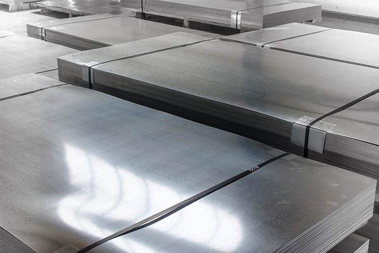
Protects components and supports the overall tower structure.
Material selection affects corrosion resistance, thermal performance, service life and maintenance cost.
The best configuration depends on process fluid, water quality, installation environment and project budget.

Coil material can be selected according to process fluid, corrosion risk, pressure drop and service life requirements.

Casing and structural materials should match outdoor exposure, corrosion environment and export project requirements.
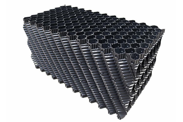
Water contact parts should resist scaling, corrosion and long-term spray water exposure.
Forced draft closed circuit cooling towers are selected when customers need closed-loop process fluid protection
with a project-specific fan and airflow arrangement.
Fans push air into the tower, supporting special project layouts.
Fan and motor access can be convenient depending on tower design.
The process fluid stays inside the coil and is not directly exposed to outside air.
Helps protect chillers, molds, compressors, furnaces and heat exchangers.
Suitable for process cooling systems requiring stable heat rejection.
Coil, casing, basin and water-contact materials can be matched to corrosion conditions.
Can be used with water or glycol solutions according to system design.
Air inlet, fan position and structure can be reviewed according to site conditions.
Thermocore can customize forced draft closed circuit cooling towers according to cooling capacity, fan arrangement,
coil design, material, airflow path, noise, voltage, corrosion environment and export shipping requirements.

For projects with special heat load, approach, wet bulb or fluid temperature requirements.
For projects requiring forced draft fan arrangement, special air inlet direction or low-noise design.
For corrosion resistance, special voltage, OEM cooperation and international shipping requirements.
Send your cooling capacity, fluid type, flow rate, inlet and outlet temperature, wet bulb temperature and project layout.
Our engineering team will compare forced draft, induced draft and other closed circuit cooling options for your project.
These FAQs are written for HVAC engineers, contractors, industrial buyers and procurement teams who need to understand
forced draft closed circuit cooling tower selection, operation and customization.
A forced draft closed circuit cooling tower is a closed-loop evaporative cooling system where fans push air into the tower, usually from the lower or side air inlet area, while the process fluid flows inside a heat exchange coil. Spray water flows over the outside of the coil, and the forced airflow supports evaporation and heat rejection. The process fluid remains isolated inside the coil and does not directly contact air or spray water.
Hot process fluid enters the heat exchange coil and remains inside the closed loop. A spray system distributes water over the outside of the coil. Forced draft fans push air into the tower and across or through the wetted heat exchange section. A portion of the spray water evaporates and removes heat from the coil surface, allowing the cooled process fluid to return to the chiller, heat exchanger or industrial equipment.
A forced draft design is often selected when the project requires a specific airflow arrangement, lower fan position, easier access to fan and motor components, or a structure suitable for special installation layouts. Because the fan pushes air into the unit, the airflow path and equipment layout can be adapted for some applications where standard induced draft tower arrangements may not be ideal.
In a forced draft closed circuit cooling tower, the fan pushes air into the tower from the inlet side. In an induced draft closed circuit cooling tower, the fan pulls air through the tower and discharges it from the outlet, commonly at the top. Forced draft designs can provide easier fan and motor access in some layouts, while induced draft designs are widely used for upward discharge and reduced air recirculation risk when the site layout is suitable.
It depends on the application. A forced draft closed circuit cooling tower keeps the process fluid inside a coil, reducing contamination risk in the main loop. An open cooling tower exposes water directly to air and usually has a lower initial cost. If fluid cleanliness, glycol operation, equipment protection or closed-loop cooling is important, the forced draft closed circuit design may be more suitable.
Forced draft closed circuit cooling towers are suitable for HVAC systems, industrial process cooling, compressor cooling, plastic injection molding, furnace cooling, chemical process cooling, power systems and manufacturing facilities where closed-loop fluid protection and a specific fan or airflow layout are required.
Important selection data includes cooling capacity, process fluid type, fluid flow rate, inlet fluid temperature, required outlet fluid temperature, local wet bulb temperature, glycol concentration if applicable, coil material preference, spray water quality, project location, available installation space, airflow constraints and noise requirement.
Yes. The process fluid is protected inside the coil, but the spray water loop is still exposed to air. Water treatment is needed to control scale, corrosion, biological growth and nozzle blockage. Poor spray water quality can reduce heat transfer performance and increase maintenance requirements.
If the project requires the lowest recirculation risk with a standard upward discharge layout, an induced draft design may be more suitable. If the customer only needs low initial cost and can accept open water exposure, an open cooling tower may be more economical. If water consumption must be minimized, a dry cooler or adiabatic cooler may be considered.
To receive an accurate quotation, send the cooling capacity, process fluid type, fluid flow rate, inlet and outlet fluid temperatures, design wet bulb temperature, project location, power supply, installation space, material preference, airflow constraints and any noise, corrosion or customization requirements.
Send us your cooling capacity, process fluid type, flow rate, inlet and outlet temperature, wet bulb temperature,
project location and airflow layout requirements. Our engineering team will help you select a suitable forced draft
closed circuit cooling tower configuration.